Lightweight Castable Lining for Petrochemical Tubular Furnaces

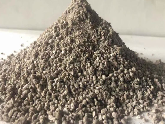
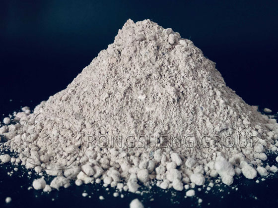
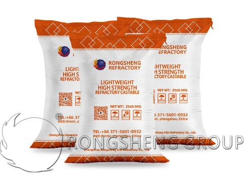
Tubular furnaces in the petrochemical industry utilize lightweight castable linings bonded with high-alumina cement, featuring a bulk density ranging from 500 to 1300 kg/m³. The castables are accompanied by a Certificate of Conformity and a Performance Index Inspection Report issued by the manufacturer—Rongsheng Refractories—and are also supplied with detailed instructions regarding installation methods.

Lightweight Castable Lining

Free Quote

    Leave Your Requirements

    Your Name (required)

    Your Email (required)

    Your Phone


    Your Requirements(required)

    Raw Materials for Lightweight Castables in Tube Furnaces

    1. High-alumina cement.
    2. Expanded shale lightweight aggregates and expanded clay lightweight aggregates.
    3. Vermiculite: calcined at a high temperature of 900–950°C; its secondary expansion rate shall not exceed 0.5%, and it must be free of impurities.
    4. Glazed perlite: subjected to high-temperature treatment at no less than 1250°C, followed by hydraulic classification and crushing; its refractoriness shall be no less than 1280°C, and its water absorption rate shall not exceed 17%.
    5. Expanded perlite: subjected to rapid high-temperature treatment at no less than 1250°C; its refractoriness shall be no less than 1280°C.
    6. High-temperature calcined bauxite grog.
    7. High-alumina brick grog: produced by crushing and screening IZ-5 grade high-alumina bricks. Lightweight brick grog. Utilization of a lightweight, heat-resistant lining composed of high-alumina cement, lightweight aggregates, and vermiculite (in a ratio of 1:2:4); specific mix proportions and performance characteristics are detailed herein.

    Packaging, Transport, and Storage of Lightweight Castables for Tube Furnaces

    1. Water used for lining construction shall have a pH value between 6.5 and 7.5.
    2. During transport, materials must be protected against moisture, properly packaged, and clearly marked.
    3. During storage, materials shall be stacked in an orderly manner according to their category, specifications, and batch number; exposure to moisture or rain is strictly prohibited. High-alumina cement must not be stacked together with other types of cement.
    4. If materials become contaminated or deteriorate due to moisture ingress resulting from damaged packaging or spillage, the affected packages must not be used.
    5. Expired materials may be used only after passing a re-inspection; however, their reuse is generally not recommended.

    Preparations for the Installation of Lightweight Castable Refractory in Tubular Furnaces

    1. Personnel responsible for the installation of the castable lining must undergo training and pass a qualification assessment before participating in the construction work.
    2. During castable installation, the ambient temperature must be above 5°C; otherwise, cold-weather protection measures must be implemented.
    3. All containers and tools used for castable installation must be thoroughly cleaned to prevent contamination by residual lime, cement, clay, or other debris.
    4. Prior to castable installation, all embedded components—such as openings in the furnace wall, refractory anchors, and sleeves—must be fully installed and verified as compliant through inspection. Any temporary fixtures that obstruct the lining installation process, or that cannot be removed after the lining is in place, must be completely removed before construction begins.
    5. Refractory anchors must be positioned and welded in strict accordance with the design specifications; the weld beads must be full and free of undercut defects. Each anchor must be individually struck with a 0.5 kg hand hammer; a clear, ringing metallic sound should be produced upon impact. For cylindrical and Y-shaped anchors, a random sample check must be performed at a rate of one anchor per 4 square meters: the top of the welded anchor is struck with a hammer and bent to a 90-degree angle; it must not fracture during this process. If it does fracture, a replacement anchor must be welded immediately adjacent to the failed one. In the event of a fracture, the underlying cause must be investigated, and appropriate remedial measures must be formulated.
    6. Before castable installation, the furnace wall must undergo thorough rust removal—either manually or using power tools—to completely eliminate oil stains, rust, and other surface contaminants from the interior surface. The metal surface, once derusted, must be protected from exposure to rain and moisture, and the refractory lining installation should commence as soon as possible thereafter.
    7. The exterior surfaces of all pipe supports, sleeves, and other metal components (excluding refractory anchors) that are to be embedded within the castable lining must—following rust removal—be coated with a 0.5 to 1 mm thick layer of asphalt, or wrapped with a 0.5 to 1 mm thick layer of ceramic fiber paper or kraft paper.
    8. If metal mesh reinforcement is required over the refractory anchors prior to castable installation, the mesh must be properly positioned and securely fastened to a flat plane to ensure its correct placement within the finished lining.
    9. Prior to castable installation, appropriate protective measures must be implemented for any embedded pipes or tubes.
    10. The surfaces of any hygroscopic masonry components that will come into contact with the castable refractory must be treated with waterproofing measures. 11 Prior to construction, the properties of the castable shall be tested; construction may proceed only after the tests have been successfully completed.
    Lightweight Insulating Castable
    Lightweight Insulating Castable

    Free Quote

      Leave Your Requirements

      Your Name (required)

      Your Email (required)

      Your Phone


      Your Requirements(required)

      Construction and Quality Inspection of Lightweight Castables for Tubular Furnaces

      Mechanical Spraying Method

      1. Prior to formal spraying operations, trials regarding the spraying process and tests on the performance of the finished product must be conducted. Finished product performance parameters shall include bulk density, compressive strength, flexural strength, and linear change after firing; formal construction may commence only after verification confirms compliance with the requirements specified in the design documents. During construction, operations must strictly adhere to the spraying process established during these trials.
      2. During spraying, the moisture content of the lining must be strictly controlled in accordance with the requirements outlined in the construction method instructions for the specific material grade being used. The lining’s moisture content shall be determined as specified in Appendix AQ2.
      3. When employing the mechanical spraying method, the lining shall be sprayed in sections, proceeding from bottom to top, and the process must be continuous until the required thickness is achieved within the designated area. If spraying is interrupted, the lining material must be immediately cut back to the surface of the wall panel; the cut face shall be perpendicular to the wall panel surface.
      4. Rebound material generated during the construction process shall not be reused for the lining.
      5. The volume of rebound material generated during the spraying process shall not exceed the limits specified in the construction method instructions for the specific material grade being used.

      Manual Ramming Method

      1. During mixing, while ensuring adequate workability, the water content should be minimized as much as possible, and the water-to-material ratio must be strictly controlled. The appropriate water-to-material ratio shall be provided by the manufacturer. Note: Water-to-material ratio = Water / (Cement + Aggregate).
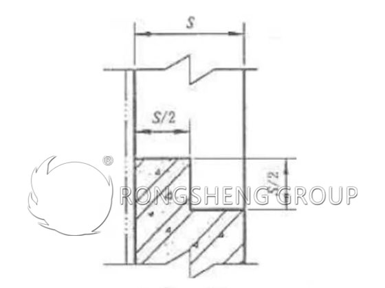
      2. During construction, the number of joints should be minimized as much as possible. If the area is large, or if other circumstances necessitate sectional construction, the joints shall be formed in a stepped configuration, as illustrated in Figure 4.2.2. For linings with a thickness not exceeding 75 mm, straight joints may be utilized. Prior to resuming construction on an adjacent section, the joint surface must be scored to create grooves, loose particles must be removed, and the surface must be moistened with water before ramming operations may continue.
      Lining seams
      Lining seams

      Quality Inspection

      1. Linings that have been applied via spraying or casting must be shaped to match the external dimensions specified in the design documents before initial setting occurs. During leveling and compaction, the application of water, cement slurry, or dry powder to the surface is strictly prohibited.
      2. During the construction process, test specimens (test blocks) shall be sampled in accordance with the specified construction process parameters. For each specific grade or mix ratio within a single project, test specimens shall be retained for inspection in batches of 20 m³; quantities less than 20 m³ shall also constitute a single inspection batch. The inspection items shall include bulk density, compressive strength, flexural strength, and linear change after firing; these results shall be recorded in the project handover and acceptance documentation.
      3. Upon completion of construction, the lining surface shall be flat and of uniform thickness; the allowable tolerance for thickness is +5 mm.
      4. After the lining has been constructed and cured, the entire surface of the lining shall be tapped using a 0.5 kg hammer at grid points spaced according to the following specifications: Furnace Roof: 610 × 610 mm; Side Walls and Furnace Bottom: 920 × 920 mm. The tapping sound should be solid; hollow sounds (indicating voids) are not permitted.
      5. After the furnace has undergone the drying-out process, the width of any cracks on the lining surface shall not exceed 5 mm, and the depth shall not exceed half of the lining thickness (1/2); furthermore, no through-cracks or interconnected network cracks are permitted.
      6. Expansion joints shall be provided in accordance with the requirements specified in the design documents. In the absence of specific design requirements, for any lining with a thickness exceeding 75 mm, a grid-patterned (cross-hatch) expansion joint—2 to 3 mm in width and 20 to 30 mm in depth—shall be provided at longitudinal and transverse intervals of 800 to 1200 mm.

      Lining Patching and Repair at Joints

      1. The patching of lining at joints shall comply with the following provisions:
        • (1) At the lining interfaces of components that were assembled and welded in sections, a margin of no less than 100 mm in width shall be left unlined on each side of the joint.
        • (2) Lining patching at the joint interface may only proceed after the welding of the joint seam and the anchoring studs has been inspected and approved.
      1. Any defects identified during the lining construction process that fail to meet the requirements of the design documents—and which would adversely affect the intended use of the lining—shall be repaired in accordance with the applicable regulations.
      2. The lining at the repair site must be chipped away down to a sound surface or the steel shell, exposing at least two anchor studs. The chipped-out section of the lining should be shaped such that it is narrower at the outer surface and wider at the inner surface.
      3. The area to be repaired must be thoroughly cleaned and moistened with water.
      4. The raw materials, mix proportions, installation methods, and curing procedures used for patching the lining at the joint—as well as for the general repair—must be identical to those employed during the original installation of the castable lining.
      5. For cracks that do not meet the specified criteria for standard repair, refractory fibers impregnated with a high-temperature bonding agent should be used as packing material, selected according to the operating temperature of the application.

      Curing of Lightweight Castable Refractories in Tubular Furnaces After Installation

      1. Appropriate curing must be performed after the installation of each layer of the castable lining. Curing procedures should strictly follow the requirements specified by the castable manufacturer. In the absence of specific requirements, water-spray curing should commence once the lining has reached its initial set—specifically, when the surface no longer adheres to the hand upon light manual pressure. The curing period must extend for a minimum of 24 hours, with water spraying performed approximately every 30 minutes; the frequency of spraying may be adjusted as appropriate based on prevailing climatic conditions.
      2. Steam curing is strictly prohibited. During the water-spray curing period, the lining should not be covered with materials such as straw bags or similar items.
      3. Upon completion of the lining curing process, an additional 48-hour period of natural air drying is required before the furnace unit may be moved or hoisted.

      Baking-out of Lightweight Castable Refractories in Tubular Furnaces After Installation

      1. Once the curing of the castable lining is complete, the ambient temperature must be maintained above 5°C. Furthermore, a minimum period of 5 days of natural air drying is required before the baking-out process may commence.
      2. The following preparatory measures must be completed prior to baking out:
        • (1) All construction work on the tubular furnace unit must be fully completed and have successfully passed final inspection.
        • (2) All necessary utility lines (e.g., fuel, air), fire safety equipment, and related facilities required for the baking-out process must be inspected and verified as being in good working order.
        • (3) All thermal instrumentation and control devices required for monitoring the baking-out process must be fully calibrated.
      1. During the baking-out process, steam should first be introduced into the furnace tubes to pre-warm the furnace for a period of 1 to 2 days, after which the burners may be ignited. Gaseous fuel is the preferred choice for the baking-out process. Throughout the baking-out cycle, the temperature rise must be uniform; the rate of temperature increase should strictly adhere to the manufacturer’s specifications or follow the prescribed baking-out curve.
      2. During the baking-out process, the steam temperature at the outlet of the furnace tubes must not exceed the following limits: 350°C for carbon steel tubes, and 450°C for chromium-molybdenum steel tubes.
      3. Comprehensive records must be maintained throughout the baking-out process, and a graph depicting the actual temperature profile (baking-out curve) must be plotted.
      4. Upon completion of the baking-out process, a thorough inspection of the refractory lining must be conducted, and detailed inspection records must be compiled. Should any damage be detected, the underlying cause must be analyzed immediately, and appropriate repairs must be executed promptly.

        Get Excellent Service

        Please Leave Your Inquiry for Rongsheng Refractory Castable & Cement! We Will Reply You In 12 Hours!

        Your Name (required)

        Your Email (required)

        Your Phone

        Your Requirements(required)

        How to Use Insulating Castables to Reduce the Surface Temperature of the Kiln Skin?

        The temperature of the shell of industrial kilns varies, and the higher the operating temperature, the higher the temperature of the shell of the kiln. In recent years, due to the requirements of environmental protection and the advocacy of energy conservation, industrial kiln enterprises have paid more and more attention to the temperature of the outer wall of the kiln skin. So how to reduce the temperature of the outer wall of the kiln skin? To reduce the surface temperature of the kiln skin, how to use insulating castables?

        Generally, if you want to lower the temperature of the kiln skin, you must improve the use of insulation materials, or thicken the insulation layer. There are many light clay bricks and light fiberboards, cotton wool, and blankets used for the insulation layer. If you use fiber insulation materials, you don’t need lightweight clay bricks, and you can’t use fiber insulation materials if you use lightweight clay bricks. However, if it is required to reduce the temperature of the kiln skin, it is necessary to do multi-layer insulation to reduce the degree of heat diffusion and reduce the temperature of the outer wall of the kiln.

        What kind of material should be used as the insulation layer when the kiln skin temperature is required to be 50°C?

        When the temperature of the kiln skin is required to be 50°C, insulating castable refractory can be used, and fiberboard can also be used as the insulation layer.

        Lightweight Insulating Castable
        Lightweight Insulating Castable

        Free Quote

          Leave Your Requirements

          Your Name (required)

          Your Email (required)

          Your Phone


          Your Requirements(required)

          The kiln skin temperature is required to be 50°C, and the temperature requirement is relatively low. If you choose fiberboard, it is not enough to use ordinary aluminum silicate fiberboard, you have to use nanometer board as an insulation layer. And it doesn’t work if it’s too thin, the minimum thickness should be 100mm. It is uncertain whether the final kiln skin outer wall temperature reduction effect will reach 50°C on the outer skin. If it is winter, it should be able to meet expectations. If it comes to summer, the temperature of the outer wall of the kiln skin may be 50℃ higher due to the influence of sunshine and weather temperature. This is affected by certain weather factors. If you use a 150mm nanoplate, there is no big problem.

          If you use lightweight castable refractory, some costs will be reduced, but the thickness should not be too small. Under normal circumstances, the thickness reaches 300mm, and the temperature of the outer skin can also be lower than 50 degrees Celsius. However, the thickness of the lightweight castable is too thick, which will affect the kiln diameter. Because the insulation layer with a thickness of 300mm, a total thickness of 600mm must be occupied on both sides of the kiln. Therefore, the usable kiln diameter will become smaller. However, from the perspective of heat preservation alone, if it is expected to reduce the temperature of the kiln skin, the temperature required by the kiln skin can also be achieved by pouring 300mm thick lightweight heat-insulating castables.

          If the height of the kiln is too high, it is unlikely to use refractory bricks for the insulation layer or the working layer. Because there may be string joints in the middle, the working layer is most likely to be poured with dense castables as the working layer. It is possible to use nano-sheets or lightweight castables for the pouring working layer. Because the outer layer of the nano-plate is wrapped with plastic, no moisture will enter, and even if the castable discharges a certain amount of water, the thermal insulation layer will not be affected. If light heat insulation castables are used and dense castables are used in the working layer, they are all constructed by pouring, and there is no problem of water discharge affecting the use of the heat insulation layer.

          Therefore, when the external temperature of the kiln skin is low, it is possible to use nano-plates and lightweight insulating castables. Only the thickness has certain requirements. The thickness of the nano-plate should not be less than 100mm, and the thickness of the lightweight castable must be constructed to a thickness of 300mm to meet certain usage requirements.

          Can Lightweight Insulating Castables be Used Outside the Furnace Shell?

          Lightweight insulating castables are used on the outside of the furnace shell and are not recommended. Because the lightweight insulating castable refractory plays the role of heat preservation and heat insulation, the main function is slowing the heat dissipation, which can save fuel and protect the furnace shell.

          Lightweight High-Strength Castable for Steel Ladle
          Lightweight High-Strength Castable for Steel Ladle

          Free Quote

            Leave Your Requirements

            Your Name (required)

            Your Email (required)

            Your Phone


            Your Requirements(required)

            If the furnace lining is not used as an insulation layer during construction, it is not recommended to use it in this way. If there is a user unit that has not made an insulation layer and has been put into production, under such conditions, in order to avoid overheating of the furnace shell, it is not advisable to make an insulation layer on the outside of the furnace shell, and then add a layer of the iron sheet on the outside.

            The reason is that there is no insulation layer and the temperature of the furnace shell is high. The insulation layer can be used for the next maintenance. If an insulation layer is made on the outside of the furnace shell and a layer of iron sheet is added, the furnace shell will also be attacked by high temperature and the service life will be shortened.

            There is a furnace type with heat-insulating material coated on the outside of the furnace shell. Due to the high temperature of the boiler, heat-insulating castables or heat-insulating bricks are used as heat-insulating layers on the inner lining. Some manufacturers also apply a layer of fabric on the outside of the furnace shell, which also slows down the temperature and heat dissipation process. This saves fuel and protects the furnace shell. There are also manufacturers who use a layer of epoxy paint on the outside of the furnace shell, but not many use this method. On the contrary, more fabrics are used.

            If the inner lining is made of light-weight insulating castable or light-weight bricks as the insulation layer, if the insulation layer is made outside the furnace shell for remedy, it will not play any role in the protection of the furnace shell, and it is of little significance to make the insulation layer. Even doing it with nanoplates doesn’t make much sense.

            Therefore, the selection of lining materials must be determined according to the temperature of the lining. Whether to use lightweight insulating castables refractory or lightweight refractory bricks or use insulation cotton and boards as insulation layers. If the furnace lining temperature does not exceed 200°C, there is no need to make an insulation layer. If the temperature exceeds 1000 ℃, it is necessary to make an insulation layer. If the temperature exceeds 1400°C, high-grade lightweight materials should be used as the insulation layer.

            Rongsheng Refractory Castable Manufacturer
            Rongsheng Refractory Castable Manufacturer

            Free Quote

              Leave Your Requirements

              Your Name (required)

              Your Email (required)

              Your Phone


              Your Requirements(required)

              Solutions to Reduce Kiln Skin Surface Temperature

              Rongsheng refractory material manufacturer is a manufacturer with rich production and sales of refractory materials. Our monolithic refractory materials offer reliable performance. It has a long service life on the refractory lining of various industrial kilns. Extend the service life of the refractory lining. Recently, our technical team is also working on the research of refractory materials that reduce the surface temperature of the kiln skin, providing cooling solutions for industrial kilns. Contact us for a free solution.

                Get Excellent Service

                Please Leave Your Inquiry for Rongsheng Refractory Castable & Cement! We Will Reply You In 12 Hours!

                Your Name (required)

                Your Email (required)

                Your Phone

                Your Requirements(required)