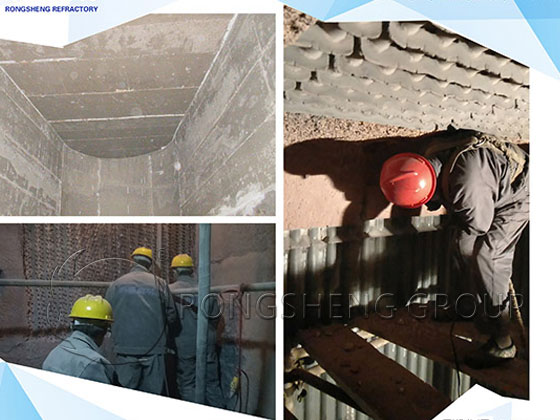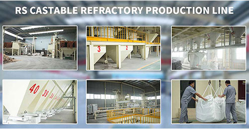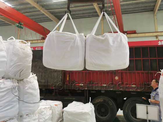
Monolithic refractories, also known as bulk refractories, are made by mixing refractory aggregates and powders of a specific grade with binders and admixtures. These refractory linings materials are used directly without undergoing forming and firing processes. Rongsheng Castable Refractory Factory, a manufacturer of unshaped refractory materials, operates an advanced, environmentally friendly, fully automatic monolithic refractory production line with an annual output of 80,000 tons. They primarily produce monolithic refractory products, including refractory castables, refractory plastics, refractory ramming materials, refractory clay, high-temperature mortar, refractory cement, and prefabricated refractory blocks. These products provide reliable support for the integral lining of high-temperature industrial furnaces.
Refractory Castables
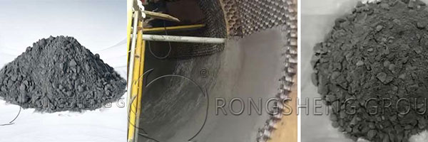
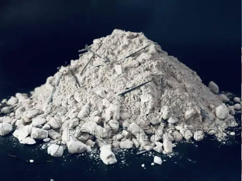
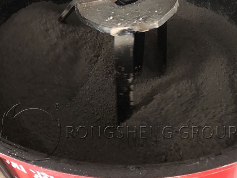
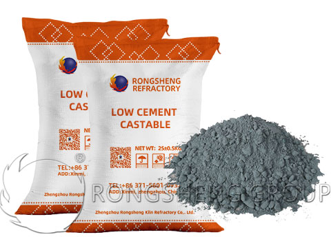
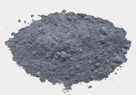
Refractory castables are a new type of refractory material that exhibits excellent fluidity after mixing with water without calcining. They are an important type of amorphous refractory material. They are a mixture of refractory aggregate, refractory powder, and binder (or admixtures) in a specific proportion. They can be shipped in bulk form or prefabricated.
The composition of castable refractory is as follows:
- Refractory aggregate is the main component of refractory castables and functions similarly to the crushed stone and sand in conventional building concrete. Refractory aggregate can be obtained from calcined clinker of various refractory materials (clay, high-alumina, siliceous, magnesian, etc.) or from various waste bricks that have been crushed to a certain degree. Aggregate particle size significantly impacts product quality. Coarse aggregate (5-20 mm) generally accounts for 35%-45% of the mix, while fine aggregate (0.15-5 mm) accounts for 30%-35%.
- Binders: These act as a bonding and hardening agent, imparting a certain strength to the product. Common binders include ordinary Portland cement, alumina cement (high-alumina cement), magnesia cement, water glass, and phosphoric acid. To ensure refractoriness and minimize volume shrinkage during use, the binder dosage should be kept as low as possible, generally 10% to 25%. Furthermore, the binder and aggregate should not form excessive low-melting products.
- Admixtures: To improve the physical and chemical properties and workability of refractory castables, appropriate amounts of these additives are often added. These include plasticizers, dispersants, accelerators, retarders, dilution agents, and gelling agents. For refractory castables exposed to high mechanical forces or intense thermal shock, adding an appropriate amount of stainless steel fiber can significantly increase the material’s toughness. Adding inorganic fiber to insulating refractory castables not only enhances toughness but also helps improve thermal insulation.
Refractory Mortar
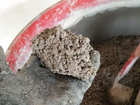
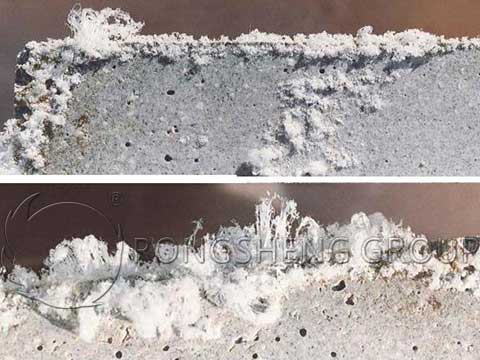
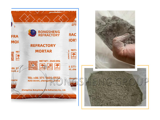
Refractory mortar, composed of refractory aggregate, binders, and admixtures, is used as a joint material for shaped products. It is delivered in dry or wet form. During construction, a mixing liquid (water or other liquid) is added to the mortar to a specified consistency. Masonry or pouring is then performed using a trowel or specialized machinery (such as a pressure grouting machine).
Refractory mortar is divided into two categories: heavy and light. Based on the binder, it can be categorized as phosphate slurry, water glass slurry, and organic binder slurry. Based on the material, it can be categorized as clay, high-alumina, magnesia, silica, or carbonaceous slurry. Its components are as follows:
01 Refractory Powder
Refractory powder is typically fine particles of refractory materials such as high-alumina, silica, and magnesia, and determines the basic properties of the refractory mortar.
02 Binder
Binders, such as Portland cement, phosphate, and water glass, are used to allow the refractory mortar to harden and develop a certain strength after application.
03 Admixtures
Admixtures are added according to specific application requirements, such as setting accelerators, setting retarders, and plasticizers.
Performance Characteristics
- Excellent Adhesion: Securely bonds refractory bricks and other refractory materials, forming a tight masonry structure and preventing the penetration of high-temperature gases and slag.
- High Refractoriness: Remains stable at high temperatures without softening or melting, maintaining masonry stability.
- Suitable Plasticity: Facilitates construction and can fill brick joints and irregularities.
- Excellent Volume Stability: Minimal volume change at high temperatures, preventing expansion or contraction that could damage the masonry structure.
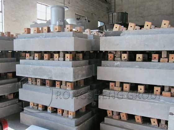
Refractory Precast Blocks
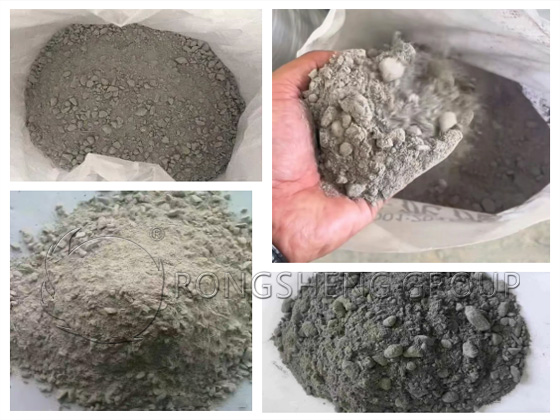
Precast blocks, which cannot be mass-produced for certain reasons, are typically prefabricated refractory block products composed of refractory aggregate, refractory powder, binders, and admixtures.
01 Refractory Aggregates
Refractory aggregates, such as high-alumina bauxite, corundum, and mullite, form the primary skeleton of precast blocks. They determine their refractoriness and high-temperature strength.
Refractory powder: Refractory powder has a finer particle size and fills the gaps between aggregates, increasing the density and strength of the precast blocks.
02 Binders
Common binders include cement, phosphate, and water glass. They are used to bind the aggregate and powder together, ensuring sufficient strength after curing under certain conditions.
03 Admixtures
Additional additives, such as accelerators, retarders, and explosion-proofing agents, are added as needed to improve the construction and performance of precast blocks.
Performance Characteristics
- Excellent refractory properties: Maintains structural stability in high-temperature environments without softening or melting. High refractoriness and refractoriness under load.
- Good mechanical strength: Through a rational formulation and manufacturing process, the precast blocks possess high compressive and flexural strength, capable of withstanding mechanical loads at high temperatures.
- High-dimensional accuracy: Prefabricated in the factory, dimensional deviations can be strictly controlled, facilitating installation and ensuring the quality and tightness of the masonry.
- Easy and convenient construction: The precast blocks can be transported directly to the construction site for installation, reducing on-site construction time and workload. They are particularly suitable for the construction of complex structures such as large industrial furnaces.
- Good thermal stability: They can withstand rapid temperature fluctuations without cracking or flaking, ensuring safety during furnace startup and shutdown.
Refractory Cement
Refractory cement, also known as aluminate cement, is a specialty cement with high refractory properties. It is used as a binder in refractory materials for the production of refractory bricks, refractory castables, and refractory spray coatings. It enables refractory materials to maintain excellent strength and integrity at high temperatures. It is also used in the linings of various industrial furnaces, such as those used in steelmaking, cement, and glassmaking.
01 Composition
It is primarily composed of calcium aluminate minerals, such as monocalcium aluminate (CaO·Al₂O₃) and monocalcium dialuminate (CaO·2Al₂O₃). It may also contain small amounts of dicalcium silicate (2CaO·SiO₂).
Performance Characteristics
- High refractoriness: It maintains structural stability in high-temperature environments, resisting softening and melting. Its refractoriness generally exceeds 1580°C.
- Early Strength and Rapid Hardening: It exhibits a high rate of early strength development, achieving high strength in a short period of time, facilitating rapid construction.
- Excellent Corrosion Resistance: Strong resistance to corrosive media such as slag and molten salt at high temperatures.
- Excellent Thermal Stability: Minimal volume change with temperature fluctuations, making it less susceptible to cracking and flaking.